Article : [DIV471]
Titre : R. AMBATIPUDI, AN-1095 - Design of Isolated Converters Using Simple Switchers, National Semiconductor, Application Note 1095, August 1998, 11 pages.
Cité dans : [DIV126]  T. LEQUEU, Librairie des fichiers PDF de composants, décembre 2025.
Cité dans :[LIVRE384]
Auteur : Ravindra Ambatipudi
Source : National Semiconductor, Application Note 1095
Date : August 1998
Pages : 1 - 11
Lien : AN1095.pdf - 11 pages, 399 Ko, Design of Isolated Converters Using Simple Switchers.
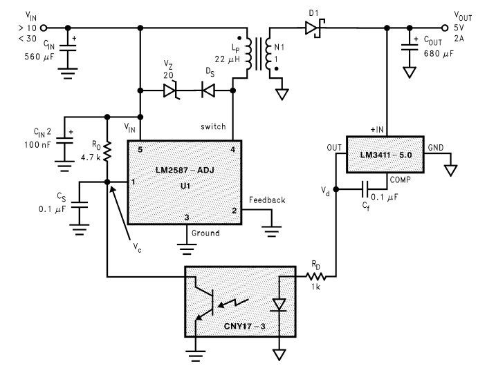
Lien : LM2587.pdf - 27 pages, 820 Ko, LM2587, SIMPLE SWITCHER ® 5A Flyback Regulator, February 2004.
Lien : LM3411.pdf - 14 pages, 791 Ko, LM3411, Precision Secondary Regulator/Driver, March 2005.
Lien : CYN17.pdf - 3 pages, 69 Ko, CNY17-1X, CNY17-2X, CNY17-3X, CNY17-4X, CNY17-5X, CNY17-1, CNY17-2, CNY17-3, CNY17-4, CNY17-5, Optically Coupled Isolator Phototransistor Output.
Lien : CYN17F.pdf - 3 pages, 66 Ko, CNY17F-1X, CNY17F-2X, CNY17F-3X, CNY17F-4X, CNY17F-1, CNY17F-2, CNY17F-3, CNY17F-4, Non-base Lead Optically Coupled Isolator Phototransistor Output.
Introduction :
Isolated converters are required to provide electrical isolation between two interrelated systems. Isolation between the power source and the load is required in certain applications in order to meet safety specifications such as UL1459, which necessitates 500V of isolation for telecom applications.
Isolation must be provided between all the input and output stages of the power converter. Thus, isolation must be provided in the power stage and the control loop. Power stage isolation is generally provided using transformer. Isolation in the feedback/control loop is often provided through an optocoupler (also known as opto-isolator).
Transformers are well suited for power stage isolation, since they are known for providing good dielectric barrier between two systems, with the ability to have multiple outputs. Transformers also allow stepping up or stepping down of the input voltage.
In isolated switching power supplies, opto-couplers are very widely used to provide isolation in the feedback loop. Optocouplers do an excellent job of isolation, minimizing circuit complexity and reducing cost.
One of the disadvantages of using an opto-coupler is its low bandwidth. The bandwidth of the converter is reduced by the introduction of an extra pole in the control loop gain of the converter. This is not a problem in conventional low frequency converters.
However, in modern high-frequency converters, the opto-coupler imposes severe restrictions on control loop bandwidth/speed.
Another disadvantage of using opto-isolator is the large unit-to-unit variation in the current transfer ratio (CTR). CTR or the coupling efficiency is defined as the ratio of opto-isolator transistor collector current to the diode current. The loop gain is directly proportional to CTR gain. Hence, high variation in CTR imposes constraints on control loop design.
Mise à jour le dimanche 25 janvier 2026 à 20 h 01 - E-mail : thierry.lequeu@gmail.com
Cette page a été produite par le programme TXT2HTM.EXE, version 10.7.3 du 27 décembre 2018.
| Copyright 2026 : |  |
Les informations contenues dans cette page sont à usage strict de Thierry LEQUEU et ne doivent pas être utilisées ou copiées par un tiers.
Powered by www.google.fr, www.e-kart.fr, l'atelier d'Aurélie - Coiffure mixte et barbier, Maelline Travel Planner - Organisatrices de voyage sur mesure, La Boutique Kit Elec Shop and www.lequeu.fr.