Fiche : [DIV061]
Titre : AN628, G. COMANDATORE, U. MORICONI, Designing a high power factor switching preregulator with the L4981 continuous mode, Application Note, STMicroelectronics, january 1999.
Cité dans : [DIV009]  Application Note ST Microelectronics, juillet 2005.
Cité dans : [DATA193] Recherche sur les PFC, Power Factor Controller, novembre 2004.
Cité dans :[DIV451]
Auteur : G. Comandatore
Site : http://www.st.com
Lien : AN628.pdf - 23 pages, 333 Ko.
Lien : L4981AB.pdf - 17 pages, 229 Ko, L4981A, L4981B, POWER FACTOR CORRECTOR, September 1998.
INTRODUCTION :
Conventional AC-DC converters usually employ a full wave rectifier bridge with a simple capacitor filter to draw power from the AC line.
This "bulk" capacitor must be big enough to supply the total power during most of each half-cycle, while instantaneous line voltage is below the DC rectified voltage.
Consequentely, the line current waveform is a narrow pulse, and the power factor is poor (0.5-0.6) due to the high harmonic distortion of the current waveform.
If a high power factor switching preregulator is interposed between the input rectifier bridge and the bulk filter capacitor, the power factor will be improved (up to 0.99).
Increasing in addition, the RMS current capability from the mains, reducing the bulk capacitor peak current and the harmonic disturbances.
Switching at a frequency much higher than the lines one, the preregulator draws a sinusoidal input current, in phase with the input line voltage.
There are several way that this can be accomplished.
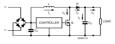
When the output voltage is higher than the input voltage (Vo > Vin), BOOST topology and continuos inductor current control mode are well suited to produce a good quality input sine current waveform.
The input di/dt is low because the inductor is located between the bridge and the switch. This minimizes line noise and the line spikes will be absorbedby the inductor.
Mise à jour le lundi 10 avril 2023 à 18 h 50 - E-mail : thierry.lequeu@gmail.com
Cette page a été produite par le programme TXT2HTM.EXE, version 10.7.3 du 27 décembre 2018.
| Copyright 2023 : |  |
Les informations contenues dans cette page sont à usage strict de Thierry LEQUEU et ne doivent être utilisées ou copiées par un tiers.
Powered by www.google.fr, www.e-kart.fr, l'atelier d'Aurélie - Coiffure mixte et barbier, La Boutique Kit Elec Shop and www.lequeu.fr.